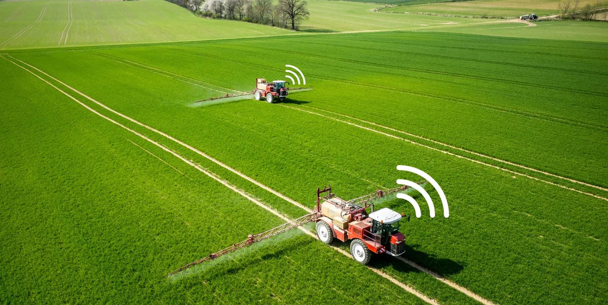
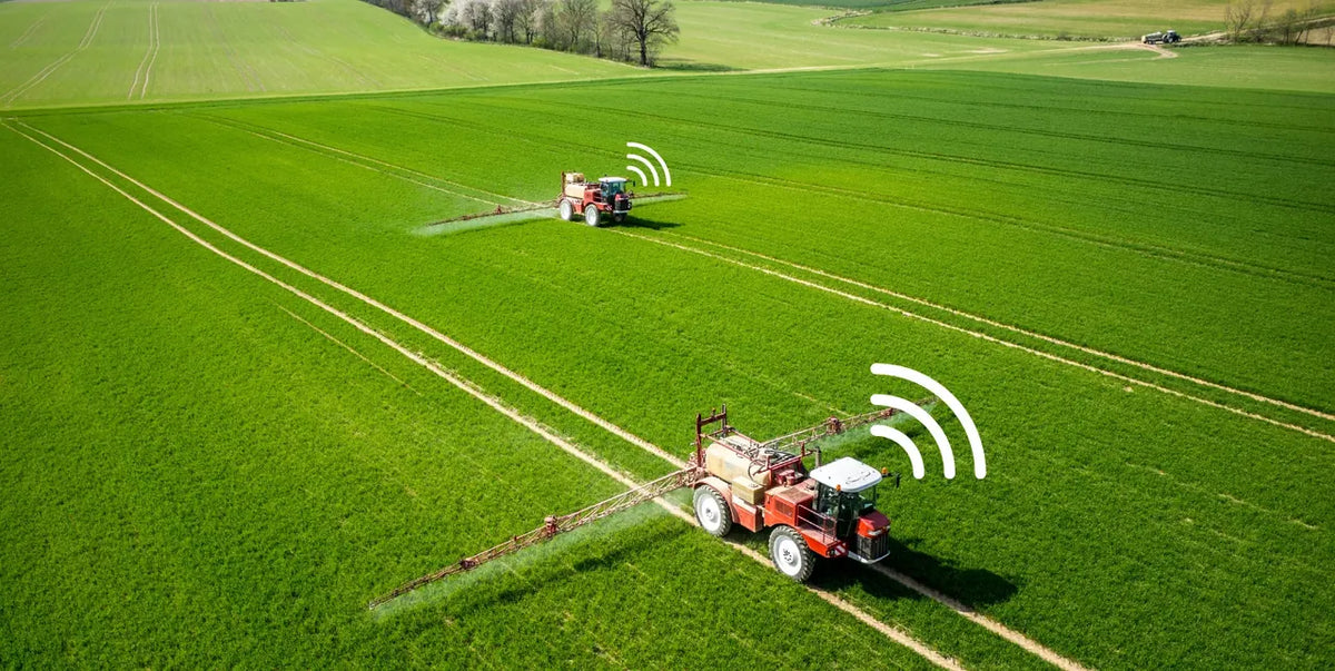
Agricultural machinery telematics is the remote collection and use of machine, position, and operation data. It connects what happens in the cab with the people managing work beyond it. When compatible CAN bus signals, GNSS position, connectivity, and farm context are combined, a tractor or harvester can contribute usable records for fleet visibility, job review, alerts, and farm management.
But connected machinery is not automatically compatible machinery. The value of any telematics installation depends on the machine, its CAN interface, the protocol in use, the data exposed by the ECU, the wiring harness, and the way the device is installed. This guide explains the full data path and the checks to make before deployment.

What is agricultural machinery telematics?
Agricultural machinery telematics is the remote collection and use of machine and operation data. A typical system combines four elements:
- Machine signals from a compatible vehicle network or interface.
- Position and time from GNSS.
- Connectivity that sends selected information to a cloud platform.
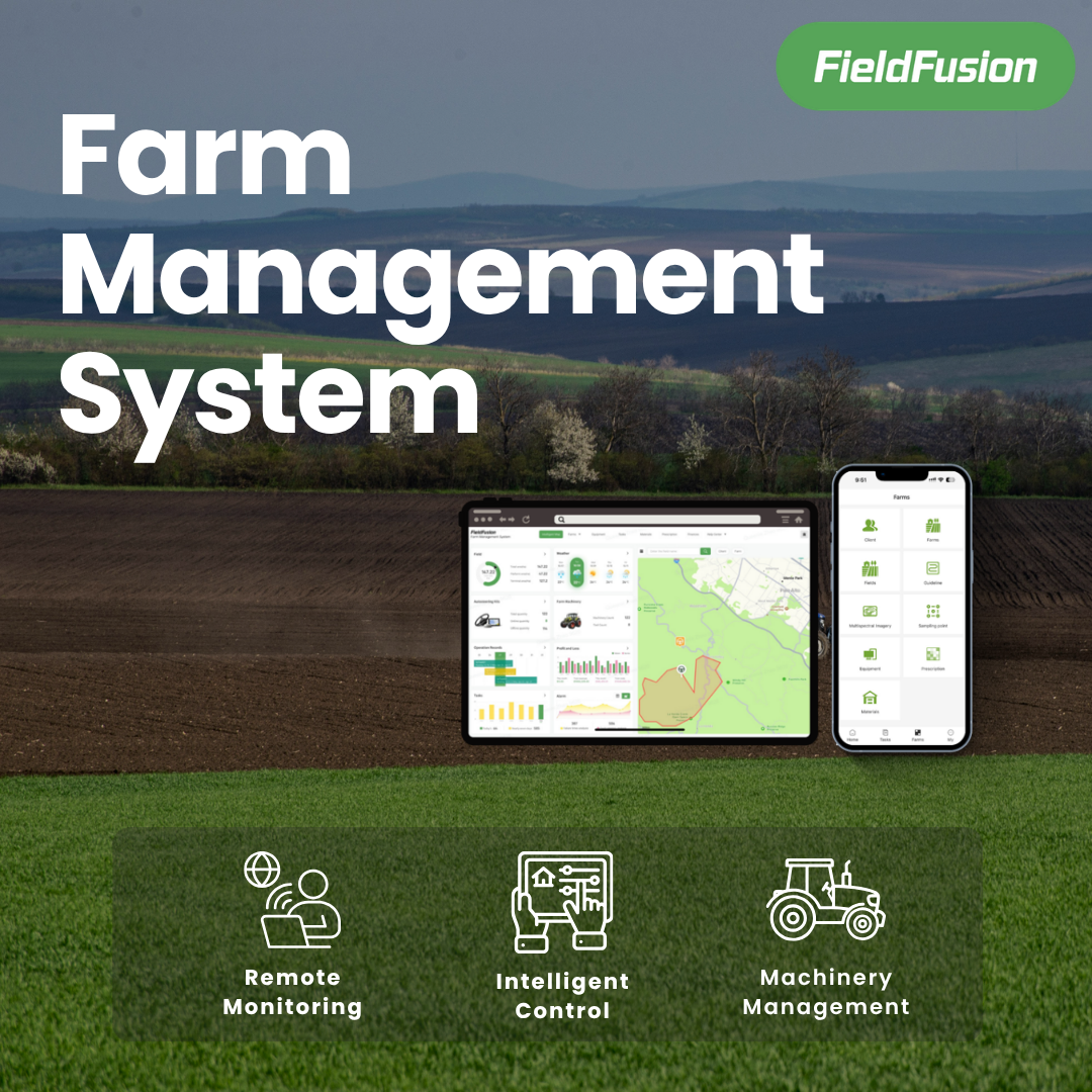
- Farm-management software that turns raw data into status, tracks, alerts, operation records, and reports. If this layer is new to you, start with this practical farm management system guide.
The hardware is only one part of the system. A useful result requires the data to be decoded correctly, associated with the right machine and implement, and placed in the context of a real farm operation.
| Telematics layer | What it contributes |
|---|---|
| Machine and ECU | Supported operating signals and fault information |
| CAN interface | Access to compatible machine messages |
| GNSS | Position, direction, time, and track history |
| Connectivity | Transfer to a remote farm-management platform |
| FieldFusion | Machine status, alerts, tracks, operation records, and reports |
How machine data moves from the tractor to a farm record
The practical data chain looks like this:
Machine ECU → CAN network → compatible telematics terminal → GNSS and time context → 4G connection → FieldFusion → operation record
The machine’s electronic control units generate operating data. A compatible terminal reads selected messages from the vehicle network, combines them with position and time, and sends the resulting information to a management platform. The platform then organizes that information around the machine, field, implement, and job.

A 2024 agricultural engineering study demonstrated a working telematics setup that collected tractor CAN-bus data, combined it with GNSS, transmitted it over 4G, and used the result for monitoring and operational analysis of field work. The important lesson is that the business value comes from the complete workflow—not from collecting isolated data points. For technical background, see the ASABE paper on a telematics system for smart farming operations.
CAN bus, SAE J1939, ISOBUS, and OBD are not the same thing
These terms are often used together, but they describe different parts of the machine-data environment.
- CAN bus is the underlying communication network used by electronic control units.
- SAE J1939 defines standardized communication practices used in many heavy-duty and off-road vehicles. SAE also publishes a J1939 recommended practice specifically for agricultural and forestry off-road machinery.
- ISOBUS, based on ISO 11783, focuses on communication between tractors, implements, and agricultural systems.
- OBD describes an onboard diagnostic system or access point. The connector shape alone does not prove which messages are available.
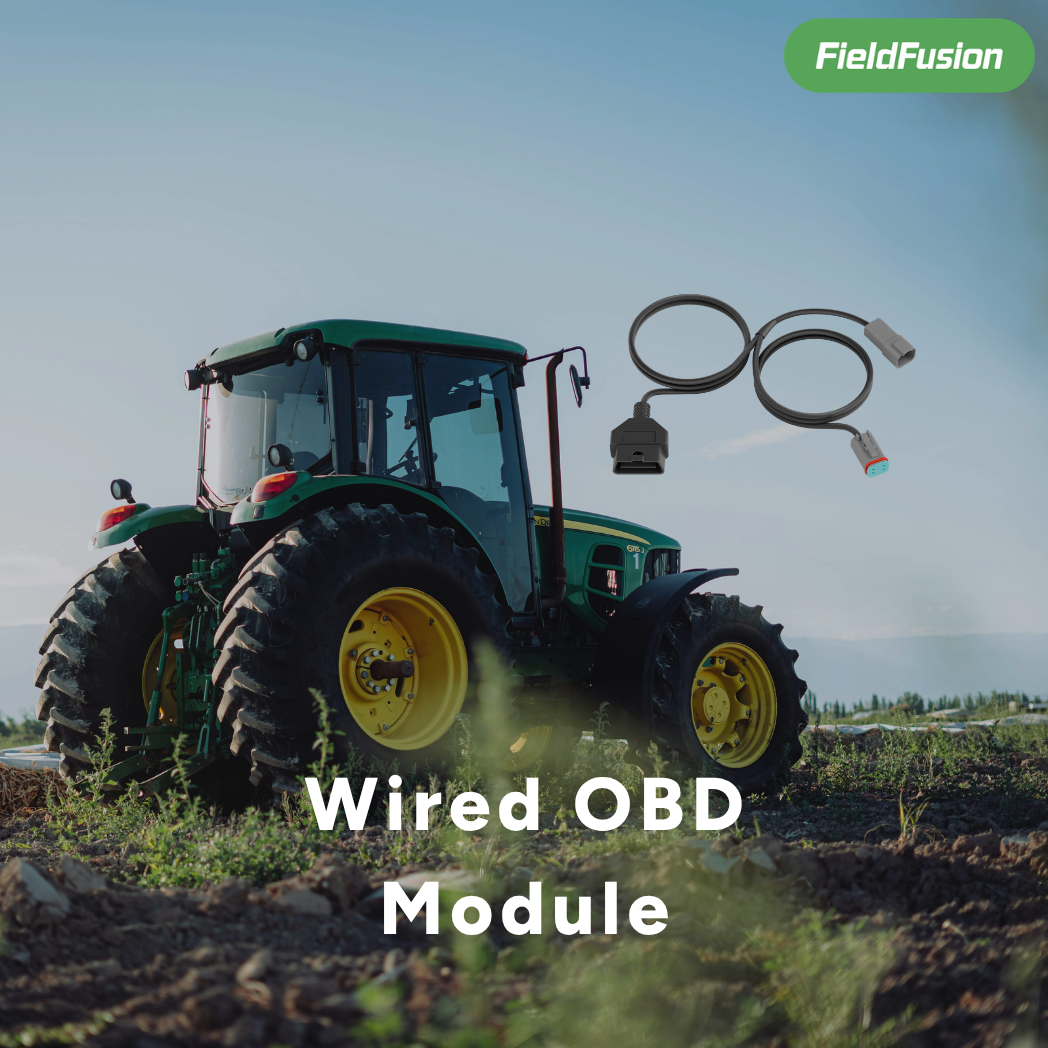
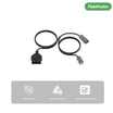
A tractor having a CAN network does not mean that every telematics terminal can read every parameter. Connector access, wiring, baud rate, protocol, ECU configuration, and manufacturer-specific message definitions all matter. A wired OBD module for tractors may provide an interface on supported machines, but it does not remove the need to verify protocol and readable parameters. The SAE J1939/2 standard page provides an authoritative reference for the agricultural and forestry context.
What data can farm equipment telematics provide?
On a compatible machine, a telematics installation may make selected information available for remote review. Depending on the machine and ECU, examples can include:
- engine speed;
- vehicle speed;
- coolant temperature;
- oil pressure;
- fuel-use information;
- operating hours;
- fault codes;
- position, direction, and track history;
- working time, distance, and calculated operation area.
This is not a universal list. The data available from one tractor may differ from another model or model year. Even two machines with CAN bus may expose different parameters. Confirm the actual readable data before making a purchase or promising a report.
Why a GPS tracker alone is not enough
A standalone locator can show where a machine is, but location alone cannot explain the full operating state. It may not show whether the engine is running, which machine parameter crossed a threshold, or which CAN-based signals are available for an operation record.
A CAN-connected agricultural telematics workflow combines location with compatible machine data and farm context. That distinction matters when the goal is to review work rather than simply find an asset.
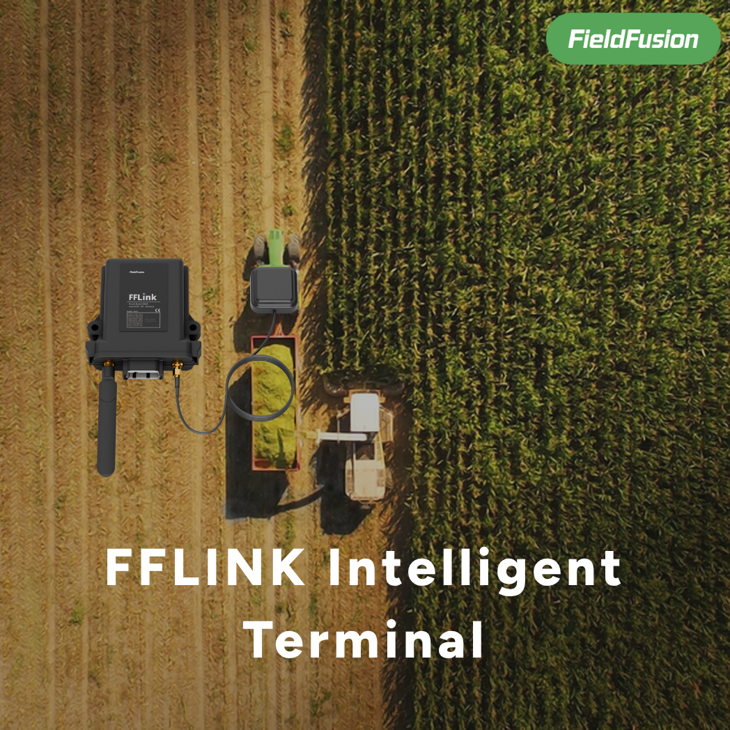
FF-LINK is deployed as a CAN-connected agricultural terminal, not as an independent GNSS locator. A compatibility check and the correct installation approach are required before deployment.
| Capability | GPS tracker | CAN-connected telematics |
|---|---|---|
| Location and track | Yes | Yes |
| Compatible engine or machine signals | No | Possible, after validation |
| Machine alerts and fault context | No | Depends on readable parameters |
| Operation records in farm software | Limited | Tracks, time, area, and supported machine data |
Five practical uses for connected farm machinery
1. See fleet status away from the field
Managers can review the location and status of compatible machines without calling every operator. This is useful when several tractors or contractors are working across different fields.
2. Build traceable operation records
Positioning tracks, timestamps, machine data, implement information, and working width can be organized into records that are easier to review after the job. The aim is not simply to collect more data, but to create a record that answers practical questions: what worked, where, when, and for how long?
3. Review working time, distance, and area
When the machine and implement are configured correctly, track data can support calculations such as working time, distance, and operation area. Implement width and working-state context matter, so setup quality directly affects the usefulness of the result.
4. Surface operating alerts
Compatible parameters can be monitored against thresholds so abnormal conditions are easier to notice. An alert is a prompt to investigate; it is not a remote mechanical diagnosis by itself.
5. Support maintenance and coordination
Operating history, faults, hours, and machine usage can give managers and service teams a better starting point for maintenance planning and fleet allocation. The terminal reads and reports supported data; it does not control the engine, hydraulics, or implement.

A compatibility checklist before you install telematics
Use this checklist before requesting a quote or scheduling installation:
- Machine identity: record the brand, exact model, model year, and region.
- Interface: identify the available CAN or diagnostic connector and confirm physical access.
- Protocol: confirm whether the relevant data uses SAE J1939 or another supported protocol.
- Readable parameters: list the data required for the management goal and verify what the ECU exposes.
- Harness and power: select the correct wiring harness, voltage arrangement, antenna position, and mounting method.
- Implement context: record implement type and working width when area and job records are required.
- Connectivity: review cellular coverage and the offline-data process for weak-network areas.
- Acceptance test: bind the device, run a real operation, and confirm the first valid record in the management platform.
This process prevents a common mistake: treating “the tractor has CAN bus” as proof that every desired data point will be available.

How FF-LINK brings machine activity into FieldFusion
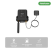
FF-LINK connects to a compatible agricultural machine, reads supported SAE J1939 data, adds GNSS position and time, and uses 4G to synchronize information with FieldFusion.
On compatible machines, FF-LINK can collect up to 19 key operating parameters. The exact parameters depend on the brand, model, year, ECU, and protocol. The terminal also supports local caching when the network is unavailable and can upload stored information after connectivity returns.
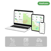
Inside FieldFusion, users can review device and machine pairing, supported parameters, alerts, tracks, and operation records. The target outcome is not a shipped box. It is a correctly installed and bound machine that produces a valid FieldFusion operation record.
A practical FF-LINK deployment workflow
- Check compatibility using the machine brand, model, year, connector, and required data.
- Select the harness and installation plan for the verified machine.
- Install and power the terminal with the GNSS antenna positioned correctly.
- Bind FF-LINK to the farm and pair it with the correct machine and implement.
- Run a real field operation rather than relying only on a bench test.
- Verify the first valid operation record, including the required track, time, area, and machine fields.
- Review the first 30 days for data completeness, alerts, connectivity, and team usage.
For farms and dealers, this workflow creates a clear handoff from compatibility assessment to installation and active use.
Frequently asked questions
Will FF-LINK work with any tractor that has CAN bus?
No. CAN bus only confirms that a vehicle network exists. Compatibility still depends on the connector, protocol, ECU, readable parameters, wiring harness, and installation conditions.
Can FF-LINK be used only as a GPS tracker?
FF-LINK is intended to be installed as a CAN-connected agricultural terminal. It should not be treated or sold as a standalone GNSS locator.
Does FF-LINK control the tractor through CAN?
No control capability should be assumed. FF-LINK reads and uploads supported machine data for monitoring and records; data access is not the same as controlling the engine, hydraulics, or implement.
Will operation data be lost when cellular coverage is weak?
FF-LINK supports local caching and recovery upload. Stored data can be synchronized when connectivity returns, subject to correct installation and system operation.
What information is needed for a compatibility check?
Prepare the machine brand, exact model, model year, region, connector photos or interface details, and the parameters or management outcome you need. This gives the technical team a much better basis for validation.
Turn compatible machine data into usable farm records
Agricultural machinery telematics works best when hardware, compatibility, installation, connectivity, and farm-management workflow are treated as one system. Start with the machine and the decision you need to support. Then verify the data path all the way to a real operation record.
Check FF-LINK compatibility for your machine by sharing the brand, model, year, interface details, and the operation data you want to use.